
The journey of a glider pilot involves two stages: the first is the learning process, and the second is the refinement of sporting skill. In the first stage, the glider pilot acquires control skills; in the second, they master the art of using their glider and the air environment for unpowered flight for distance, height, or speed along a specific route.
The variety of flight exercises at this stage, different teaching and training methodologies, local conditions for flight operations and glider maintenance, and a number of other factors, necessitate a whole range of gliders for various purposes. In our opinion, DOSAAF glider pilots require, at a minimum, the following types of gliders: single and two-seater club gliders, similar ones for training organizations, light gliders, international standard class gliders, training gliders for distance flights, and aerobatic gliders. For individual teams or record-holding groups, record gliders for distance flights and special record gliders for high-altitude flights are necessary.
The BRO-12 Light Glider: Design and Purpose
Light gliders should occupy a prominent place in this array. In our view, the light glider is a transitional type, necessary for the individual training of young, still insufficiently experienced pilots after completing their instruction on single-seater or two-seater gliders in clubs and training organizations. It allows for practicing duration, altitude, and limited distance flights to improve piloting technique and practically study the air environment.
A light glider should be able to be launched easily with a medium-powered auto-launch system to an altitude that allows for transition into thermal currents. It needs to be simple in all respects, inexpensive, and accessible for gliding clubs or self-organized gliding stations. Based on these fundamental requirements, the author of this article developed the new design for the light glider BRO-12.
The first prototype of this glider was built by the team of the Kaunas Gliding Station DOSAAF in 1957. The glider was flight-tested, received approval, and was accepted for serial production.
The light glider BRO-12 (see color insert) boasts the following main characteristics: empty weight – 137 kg; flight weight – 227 kg; wing loading – 20 kg/m²; minimum sink rate – no more than 0.3 m/sec at a glide speed of 55-60 km/h; maximum glide ratio – not less than 20 at a speed of 65-70 km/h.
Construction and Aerodynamic Features
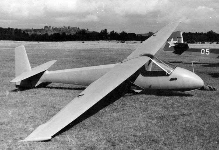
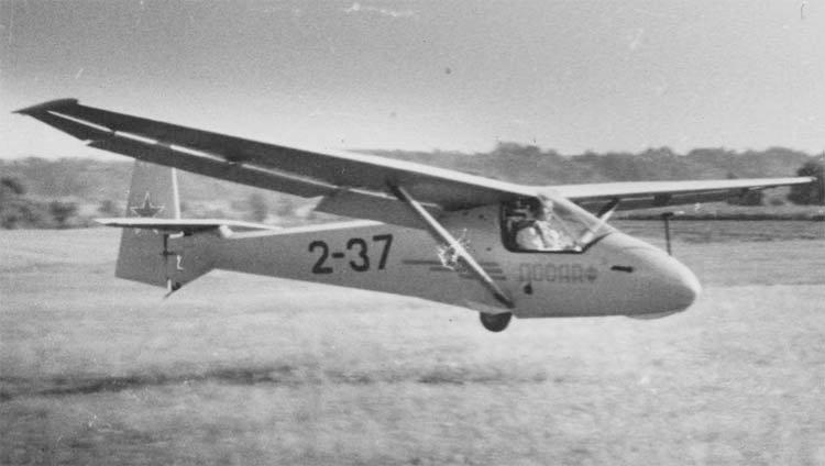
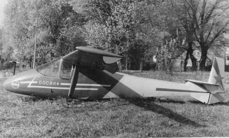
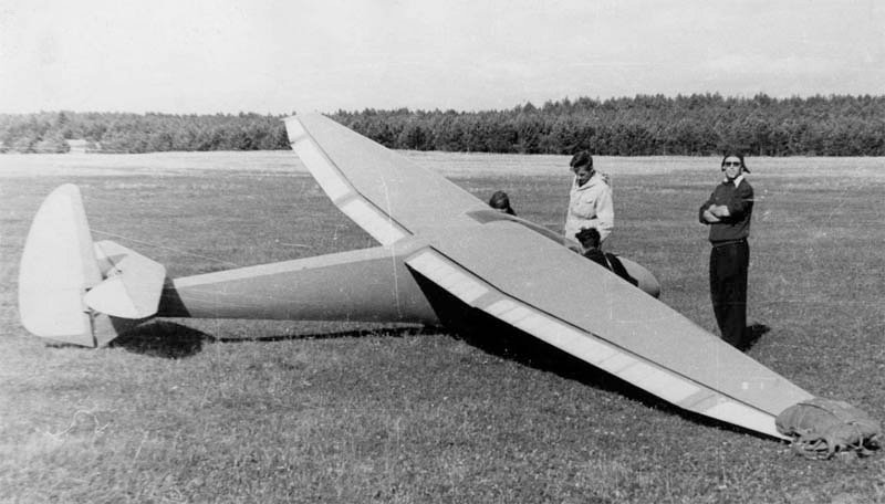
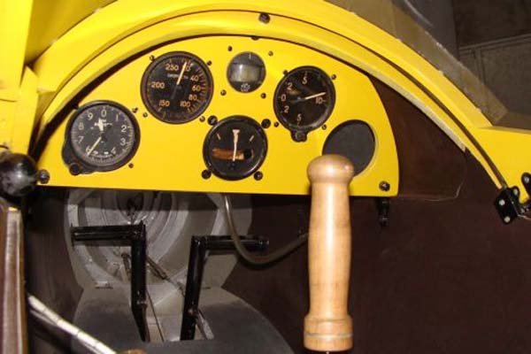
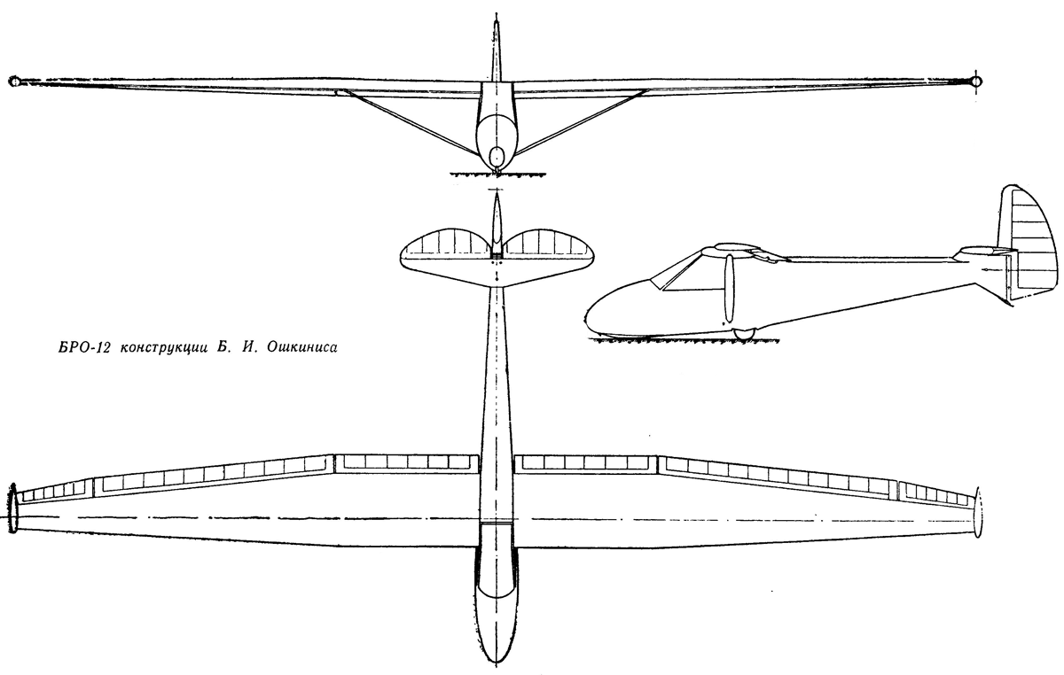
The BRO-12 is a single-strut high-wing monoplane of wooden construction. It features a complete set of instruments. The pilot’s cockpit is open at the sides, and the seat is designed for a PNL-45 parachute. The landing gear is a single wheel. The wing consists of two half-wings. To achieve the maximum lift coefficient (to ensure maximum height when launched with an auto-start system), a full-span slotted wing design is employed. Flaps and ailerons are of the suspended type, thus the main wing has no cutouts, maintaining an undistorted profile throughout and a sharp, straight trailing edge.
The wing has only one spar. Instead of a second, auxiliary spar, there is a reinforced trailing edge. The strut attachment points are spaced 2 m from the glider’s axis. Up to the strut attachment, the wing is straight, and the tips are trapezoidal. The main chord is 900 mm, and the tip chord is 300 mm. The wing profile is Göttingen 549 with a slight modification at the rear bottom. Despite a profile thickness of 13.5%, due to the small chord, the spar height is modest, and the wing is quite flexible.
The spar is of a box-type construction. The spar flanges are glued from six 5×40 mm strips, with wall thicknesses up to 3 mm. At points of maximum load, the main spar box has additional glued outer strips with a 20×40 mm cross-section, whose thickness gradually tapers off over 1 m towards the wing root and 2 m towards the wingtip. The spar cross-section precisely fits the profile, so the spar occupies the entire thickness of the wing.
The rib set of one half-wing consists of 4 reinforced and 41 simple ribs. There are no half-ribs. Ribs are spaced every 130-125 mm. Rib No. 1, at the wing root, is especially reinforced, of a box-truss type, and fits onto the wing spar. At the spar’s passage point, the rib flanges are externally reinforced with additional strips. All this effectively transmits the wing’s torsional moment to the rear wing-fuselage attachment point. All other ribs are cut at the spar’s passage point.
Reinforced ribs No. 14, 26, and 38 are made of 10 mm plywood; they also serve as brackets for the aileron suspension. Simple ribs have an I-beam cross-section. The webs are made of 1 mm plywood, with the edges outlined on both sides by 5×5 mm strips. For lightening, circular holes are made in the rib webs. At the wing’s leading edge, all ribs are connected by a 10×15 mm stringer.
A special 10 mm plywood rib is fitted to the wingtip, connecting the last ribs of the wingtip and the tip flap, and also serving as a ground support. This rib is covered with pieces of foam plastic which, after appropriate processing, form a cigar-shaped wingtip fairing. The wing is entirely covered with plywood of 1 to 1.5 mm thickness.
The plywood layer is placed at 45° relative to the spar line. The plywood is spliced at the middle of the spar and, mainly, on the reinforced ribs. The plywood skin and small spans between the ribs ensure good wing profile execution and impart high torsional strength. The entire wing skin is covered with percale (AK-20 glue). The surface is coated with nitro paints, sanded, and polished.
The suspended wing elements consist of six parts, three in each half-wing. The first parts, 1700 mm long, are the flaps and are controlled by a separate sector on the left side of the pilot’s cockpit. The middle parts, 3200 mm long, are the ailerons. They are semi-differentially connected and linked to the flap control. Ailerons deflect along with the flaps, so the aileron deflection angle is 1/3 of the flap deflection angle. Flaps and ailerons have the same profile, all their ribs are identical, and the spars have the same constant height. There is no wash-out.
The third parts – the wingtip flaps – are fixed rigidly. Therefore, when ailerons are operated, the profile at the wingtip does not change or distort, and the ailerons cannot touch the ground. The entire wingtip, as a whole, has good streamlining, which ensures the damping of possible vibrations at high flight speeds. The wingtip flap has a trapezoidal shape and a 6-degree twist. Flaps and ailerons are positioned so that the main wing profile overlaps the flaps by 50 mm, and the axis of rotation is located so that when ailerons are deflected, the gap at the wing’s trailing edge almost does not change and is about 15 mm.
There are no interceptors or other types of airbrakes on the wing of the experimental glider, thus the integrity of the wing and profile is fully preserved. Airbrakes are installed on the wing struts.
The fuselage of the BRO-12 glider is of wooden construction. The front section is oval, and the tail section is triangular, with somewhat convex sides. There is no pylon. The rear part of the fuselage is quite flat, and under the stabilizer, it transitions into the fin plane. Ahead of frame No. 1, there is a removable front fuselage cover. Along the entire front part of the fuselage, from below to the wheel housing, runs a strong rail which, between frames No. 1-5, protrudes from the general oval cross-section of the cockpit and forms a solid front skid, sheathed with sheet steel. At the front end of the skid, a tow hook is located along with a hook for a shock absorber.
Between frames No. 3 and No. 4, pedals of a special, fairly simple design are installed. Depending on the pilot’s height, the pedals can be repositioned. The side walls of the pilot’s cockpit are double-layered with a smooth inner surface. Up to frame No. 5, the cockpit is covered with plywood from above. The instrument panel is removable and installed at frame No. 6. On the left side, near frame No. 7, are the sectors for controlling wing mechanization and tow hooks. Between frames No. 6 and No. 8, a removable seat is placed.
At frame No. 8, under the seat, a tube runs across the cockpit, at the ends of which are side locks for launching the glider with an auto-start system. The locks are designed so that the rope releases automatically as soon as its angle approaches 90°. By rotating the tube connecting the locks, the rope can be disengaged at any moment of the glider launch.
Frame No. 9 is the main one. It is specially reinforced, and a through-node for strut attachment is fitted to its underside. On the upper part of the main frame, nodes for wing attachment are installed. In the middle part of this frame, there is a cutout, which is covered with canvas. The upper part of the parachute fits into the resulting depression. Slightly above, there are openings through which the shoulder harness straps pass. The lap belts are attached below, on frame No. 8. The pilot’s cockpit is open at the sides. The cockpit sides are low, have soft contours, and the pilot’s hands can rest freely on them. A removable canopy covers the cockpit only from the front and top. The canopy protects against drafts, provides good forward and upward visibility, and does not hinder downward, sideways, and rearward visibility at all. When launching with an auto-start, the presence of the rope in the side locks can be checked visually or by hand. The canopy consists of a wooden frame and sheet plexiglass or celluloid 2-2.5 mm thick. There is a device for emergency jettisoning of the canopy.
The wheel housing is arranged between frames No. 9 and No. 10. The wheel dimensions are 255 x 110 mm. Frame No. 11 is also reinforced – this is necessary for joining with the wing’s trailing edge. From above, between frames No. 9 and No. 11, the fuselage is not closed; there are only structural braces in the horizontal plane. In this part of the fuselage, almost all aileron and flap control units are mounted. They are easily accessible for inspection through the removable center wing cover. A box for the barograph is also located there.
The structural part of the fuselage consists of a horizontal power truss, a set of light frames, and plywood skinning. Frames No. 12-20 have a V-shape with somewhat steep sides. These are 1.5 mm thick plywood cutouts, whose outer edges are outlined on both sides by 6×6 mm strips. Frames No. 21 and No. 22 are reinforced; the stabilizer is installed and attached to them. Additionally, on frame No. 22, a three-arm rocker for elevator control and guiding rollers for rudder cables are installed. Frame No. 24 features rudder hinges.
The truss is built separately, and the frames are then installed on it. The lower corners of the frames are connected by a strong triangular-section rail. The fuselage sides between frames No. 11-19 are covered with 1.5 mm plywood, and behind frame No. 19, with 2 mm plywood. Below, at the last frame, a spring-type tail skid is installed. The upper part of the fuselage tail section is covered with 1 mm plywood. This is done last, after internal painting and control wiring installation.
The stabilizer is cantilevered. It consists of a spar, 24 ribs, and a leading edge stringer. The stabilizer is entirely covered with 1 mm plywood. The stabilizer is attached to the fuselage at three points using a special joining and locking scheme. The elevator is fabric-covered and consists of a spar, 14 ribs, and a solid round-section leading edge. The elevator area is 45% of the total horizontal tail area. The elevator has four hinges (two in the middle and one on each tip). There is a mass balance, installed on the three-arm control rocker. The rudder consists of a spar, a set of ribs, and a compensator. The rudder is fabric-covered and suspended on two hinges, with a duralumin horn.
Glider span: 12 m; length: 5.9 m; wing area: 11.3 m²; aspect ratio: 12.7. Thus, unlike well-known types, the wing of the new BRO-12 glider has a continuous longitudinal slot, formed by the trailing edge of the plane and the suspended ailerons and flaps. This arrangement of the surface elements allows for changing the wing profile in flight. Thanks to this, the glider is able to maintain its maximum glide ratio at various speeds. When launched with an auto-start, it gains significant altitude, from which it easily transitions into thermal currents.
Performance and Operational Insights
The BRO-12 glider is designed to perform a complex of exercises according to the standards of the 2nd and 1st sports categories. During factory tests, it easily took off using a shock absorber, behaved very stably when towed by an aircraft, and during auto-launch. In free flight, the effectiveness of all controls is sufficient and normally coordinated. The glider proved to be very efficient in flight.
Accumulated flight experience with the BRO-12 glider indicates that it is beneficial to raise the flaps from the neutral position at speeds above 80-90 km/h, and extend them at minimum speeds. The wing mechanization provides a particularly noticeable effect during auto-launch. With the help of a Nazarov winch, the glider reaches an altitude of up to 550 m, and with wing mechanization applied, over 700 m.
Based on the results of the glider’s experimental operation, some further modifications will be made to the design. The introduction of this new light glider will contribute to the further mass development of Soviet gliding.
Technical Specifications
| Modification | БРО-1 2 |
| Wingspan, m | 12. 00 |
| Length, m | 5.90 |
| Height, m | 1. 50 |
| Wing area, m2 | 11. 30 |
| Empty weight | 137 |
| Normal flight weight | 227 |
| Cruising speed, km/h | 60 |
| Max. aerodynamic quality | 20 |
| Minimum rate of descent, m/s | 0.80 |
| Landing speed, km/h | 45 |
| Crew, crew members | 1 |
Image and diagram gallery of the BRO-12 Glider
 BRO-1 |
 BRO-1 |
 BRO-1 |
 BRO-1 |
 BRO-1 |
 BRO-1 |