
A New Standard in Gliders
In January 1957, the International Aeronautical Federation (FAI) introduced a new class of gliders, dubbed “standard” or “limited.” These gliders featured a limited wingspan, no flaps, and non-retractable landing gear. The Br 901, developed around that time, proved too expensive and complex for widespread adoption by aero clubs.
In July 1957, the Breguet company proposed a “transitional” glider project that met the requirements of this new class. This glider, ordered in December 1957 and first flown on April 15, 1958, was designed by a team led by Messrs. Jarlot and Cail, who had recently begun operations in Aire-sur-l’Adour.
Development and Production Challenges
Tests of the Br 905 were conducted very quickly. A mere month and a half after its first flight, the Br 905 was delivered to Saint-Yan, and by August 1958, it was able to participate in the World Championship held in Poland. In these competitions, flown by pilot Labarre, the glider achieved an eighth-place finish.
A series of fifty Br 905 S Fauvette gliders was initiated at the Aire-sur-l’Adour factory. These were to be the last gliders produced by Breguet, with the series completed at the Anglet factory before the glider division closed in May 1960.
Breguet hoped to sell the gliders as assembly kits, or “Meccano boxes,” for gliding enthusiasts. A second Br 905 prototype was manufactured in Béziers based on this kit concept. However, this initiative proved unsuccessful, as the lack of state subsidies prevented the kit price from matching that of the factory-built Br 905.
During operation of the Fauvette gliders, it was discovered that their mixed wood-metal construction was difficult to maintain and repair. This was the sole, but significant, drawback reported by Br 905 operators, particularly concerning the wing-fuselage connections or the rear fuselage section. The flaw was so severe that Breguet was compelled to recall purchased gliders for correction at the Anglet factory in 1961. After these rectifications, the Br 905 fully satisfied glider pilots.
Innovative Technical Features
The glider’s wing, which utilized a new profile from the NACA 63 aerodynamic series (as in Br 901-904), was single-spar with a leading edge in a sandwich construction of plywood and Klégecell PVC foam. The rear part of the wing was reinforced with ribs and covered with fabric. There were no flaps, and the control surfaces consisted solely of non-slotted ailerons. The aileron control system was rigid, using cables within the fuselage. Air brakes were positioned on both the upper and lower wing surfaces.
The glider’s fuselage comprised three elements: front, central, and rear. The front and central sections featured a truss structure welded from steel tubes and covered with plastic skin (cast polystyrene and laminated fiberglass). The rear section was a sandwich construction of plywood and Klégecell PVC foam. The front fairing was made of plastic, and the teardrop-shaped cockpit canopy was manufactured from a single piece of plexiglass.
The glider’s design was intended to ensure not only quick and easy replacement of damaged parts but also to receive state preferences. However, it later became clear that this technical solution was flawed, as it led to increased glider weight and structural complexity. The main landing gear was fixed and covered by a plastic fairing, equipped with a single wheel measuring 220 × 80 mm.
The “butterfly” tail was the most notable innovation in the glider’s design. It consisted of fixed surfaces and movable rudders. Structurally, the fixed surfaces were caissons. The rudders were single-spar; the spar and ribs formed a lattice structure covered with fabric, and they featured horn balance.
The fixed surfaces and rudders were interchangeable. To achieve good rudder control and soft landings on unprepared surfaces, the dihedral angle of the tail surfaces was 90°, an angle almost unused worldwide before then. Initially, the air brakes interfered with the tail, but this issue disappeared shortly after they were relocated closer to the wingtips.
The glider’s equipment included a radio and oxygen apparatus. Disassembly of the glider was particularly simple and quick. The two wing panels and two tail elements could be detached from the fuselage. The maximum strength coefficient was 8, which was lower than that of the Br 901 and Br 904 (10) and the Br 900 (12).
Technical Specifications
| Modification | Br.905S |
| Wingspan, m | 15.00 |
| Length, m | 6.22 |
| Aspect ratio | 20.00 |
| Wing area, m2 | 11.25 |
| Wing loading, kg/m2 | 24.50 |
| Empty weight | 155 |
| Normal takeoff weight | 275 |
| Maximum takeoff weight | 460 |
| Maximum speed, km/h | 220 |
| Max. glide ratio | 30 |
| Speed for max. glide ratio, km/h | 78 |
| Minimum sink rate, m/s | 0.65 |
| Speed for min. sink rate, km/h | 56 |
| Max. operational load factor | 5.33 |
| Crew | 1 |
Image and diagram gallery of the Breguet Br.905 Fauvette
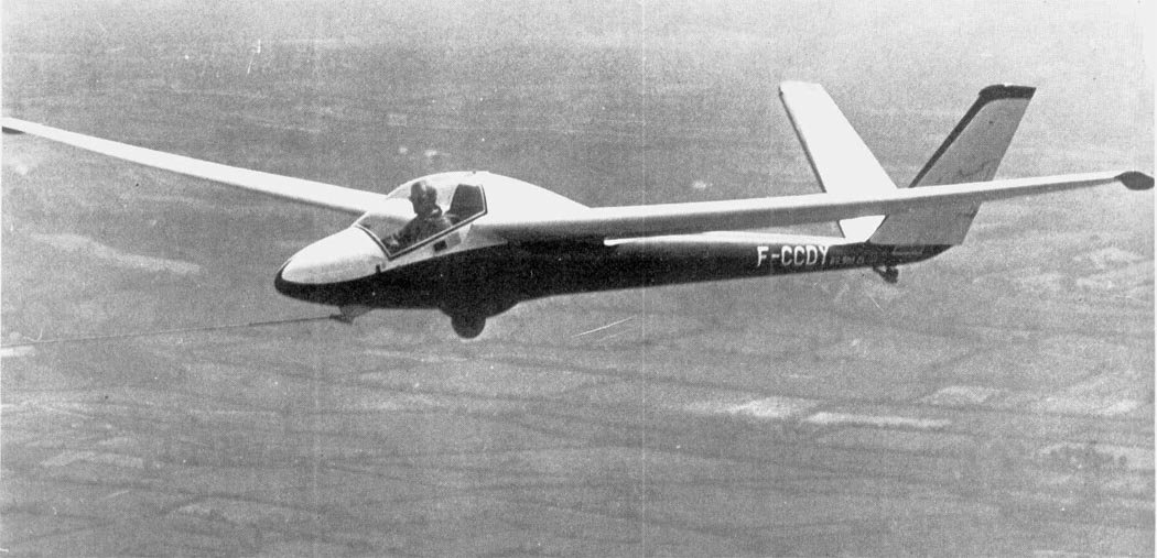 Br.905 Fauvette |
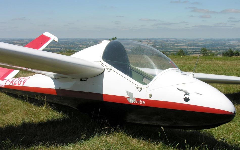 Br.905 Fauvette |
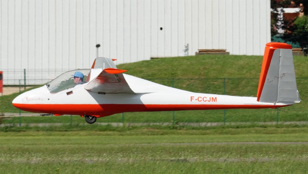 Br.905 Fauvette |
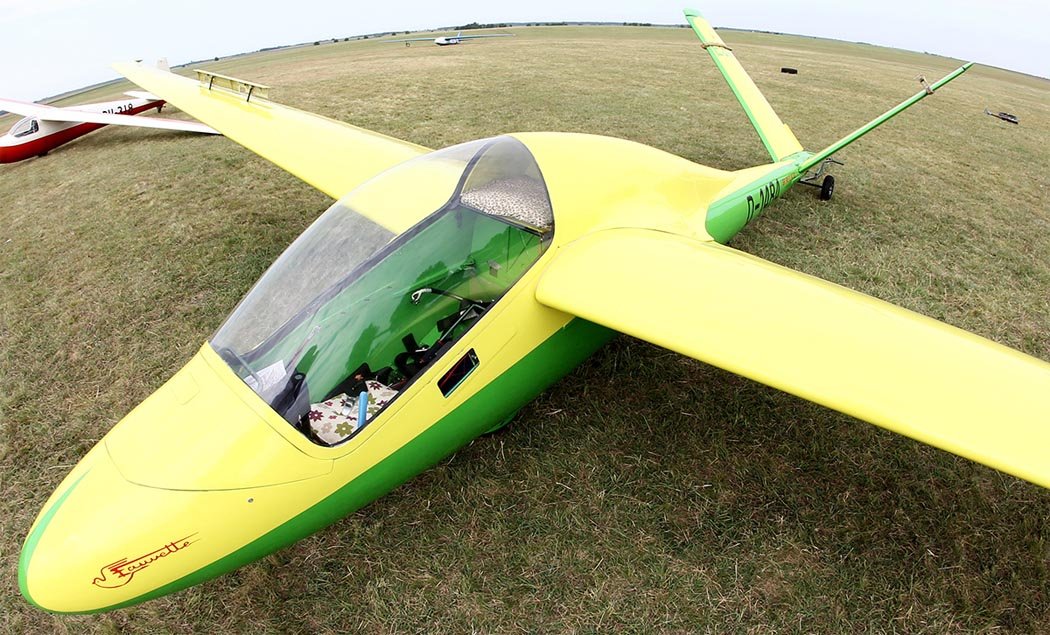 Br.905 Fauvette |
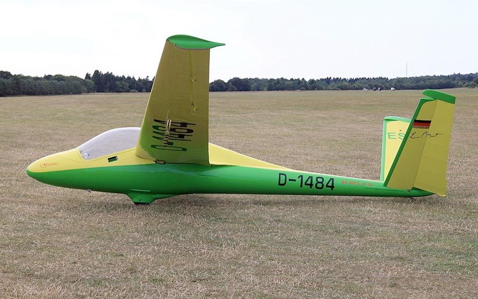 Br.905 Fauvette |
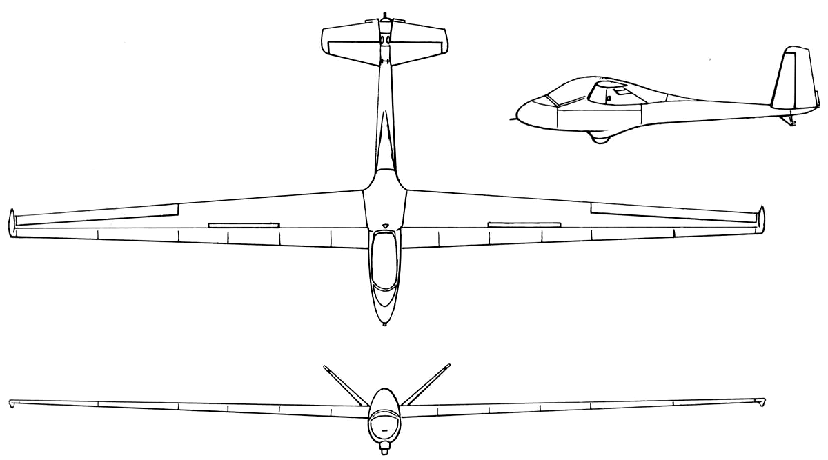 Br.905 Fauvette |
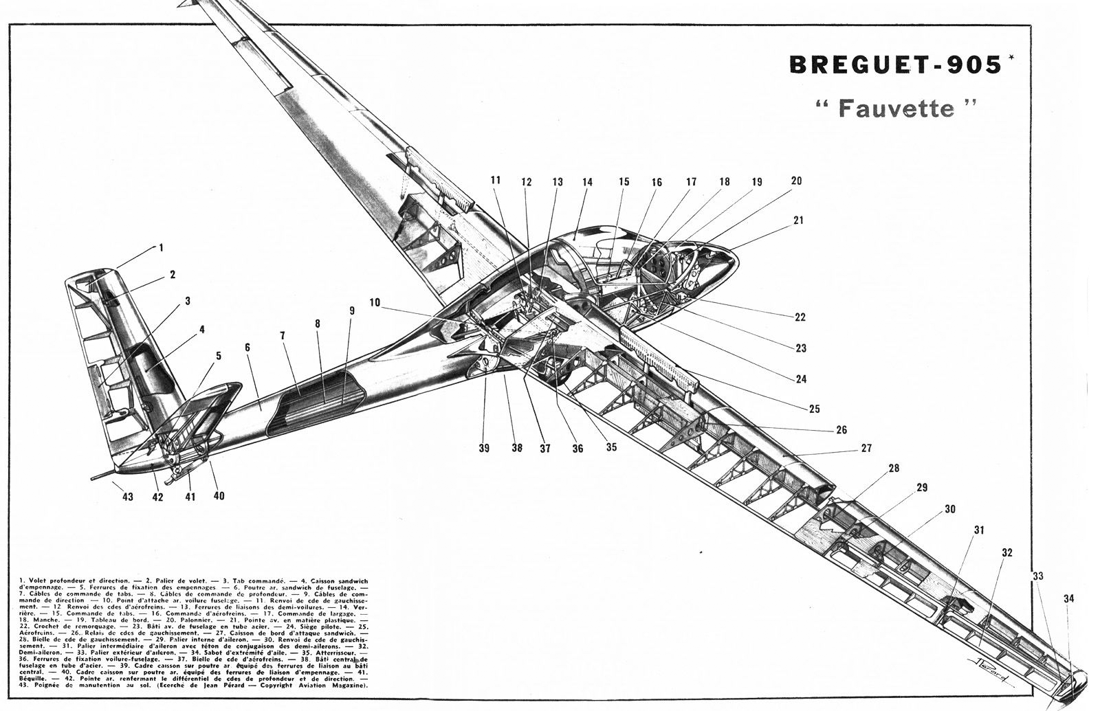 Br.905 Fauvette |
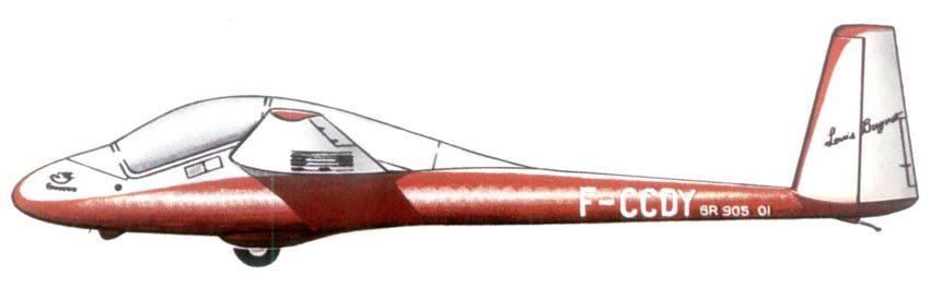 Br.905 Fauvette |
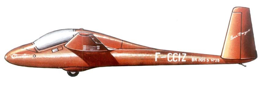 Br.905 Fauvette |