
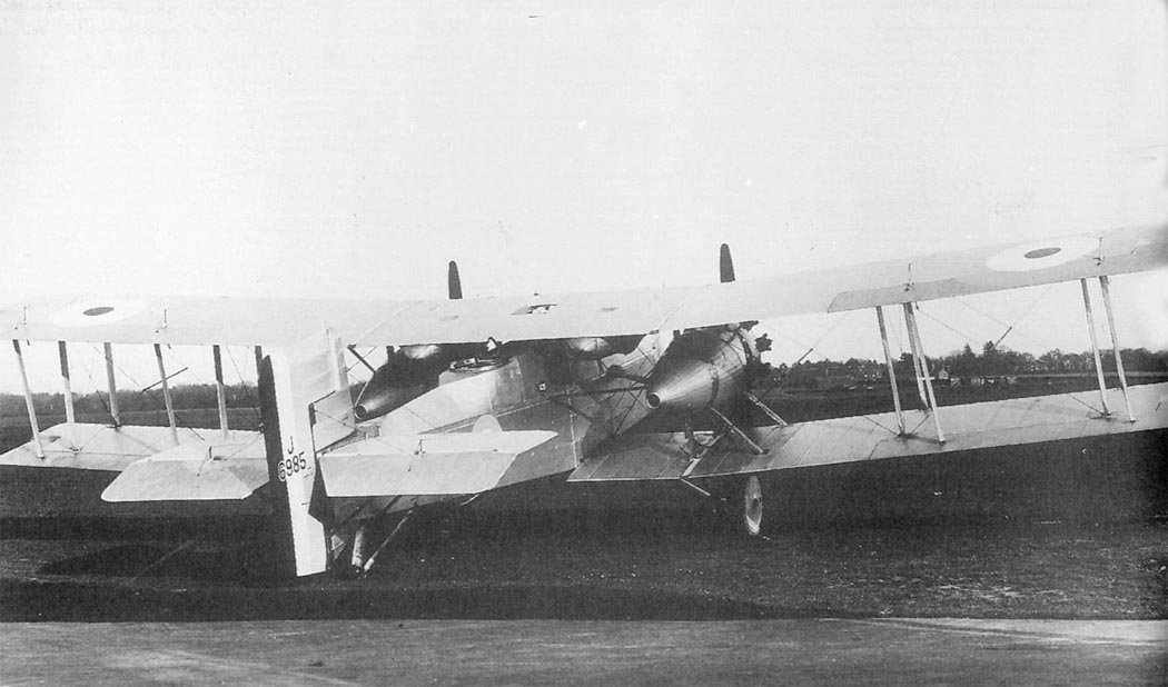
Boulton & Paul received another opportunity to further develop its steel construction, and under Air Ministry specification 30/22, another twin-engined medium bomber was ordered. The result was the P.25 Bugle – an aircraft that retained the basic layout derived from the Bourges and continued by the Bolton. Initially, two prototypes (military registration numbers J6984 and J6985) were ordered, each equipped with two 400 hp nine-cylinder air-cooled Bristol Jupiter II/III radial engines.
Innovative Design and Construction
The new aircraft had a wingspan of 65 feet 0.5 inches (19.825 m), which was larger than that of the Bolton. The four ailerons of the P.25 Bugle’s wings were connected by struts rather than cables, as in earlier designs. Self-aligning bearings were introduced to eliminate aileron stiffness when the wing flexed.
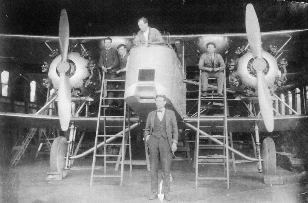
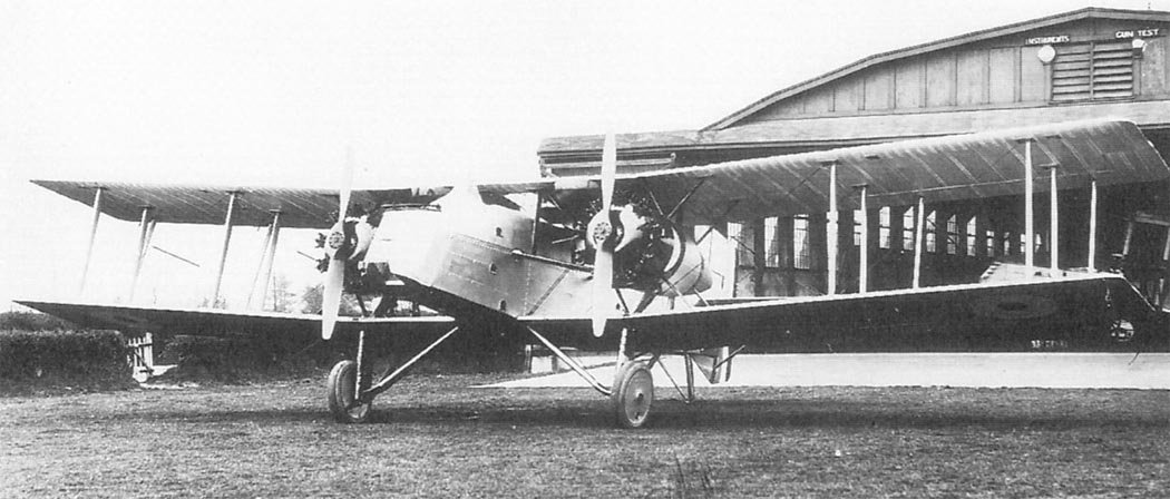
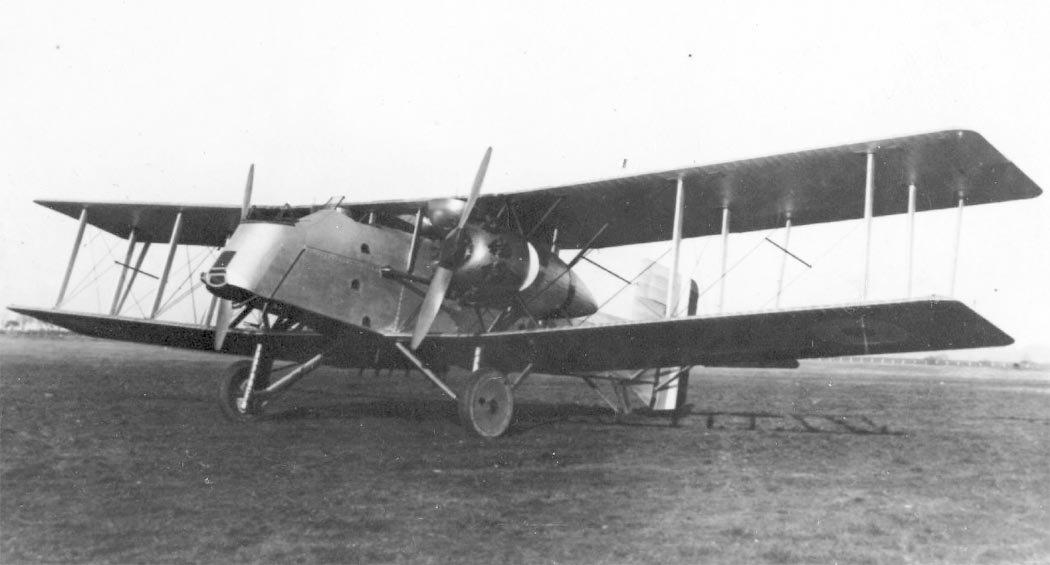
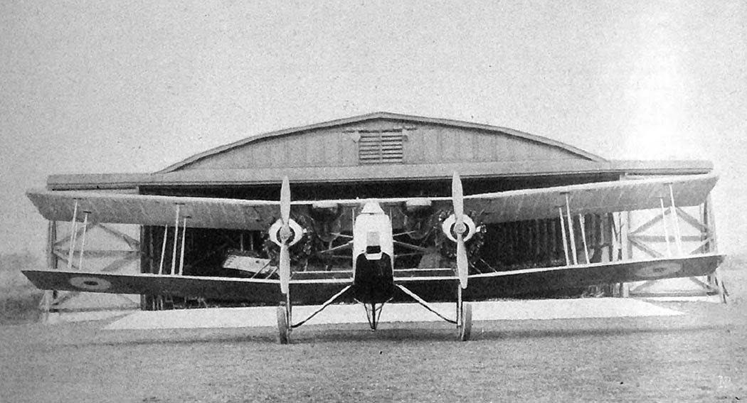
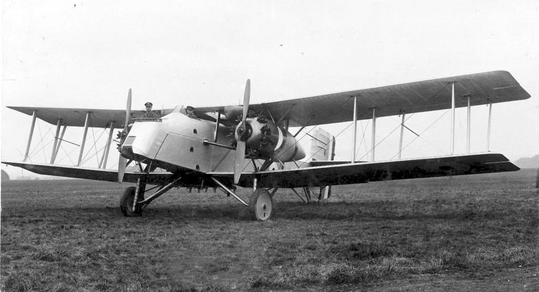
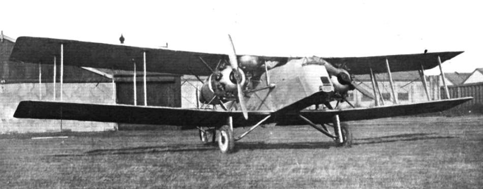
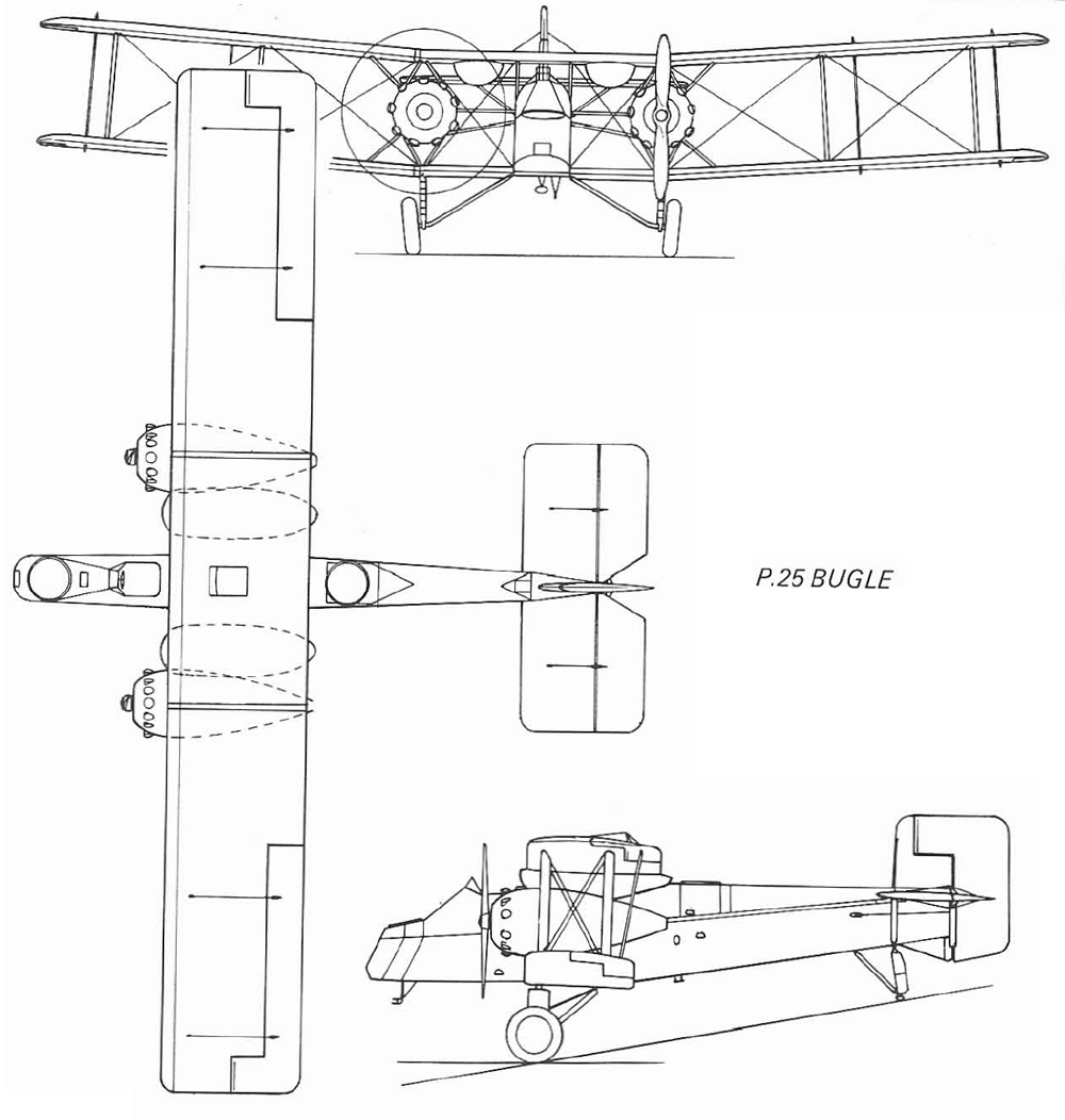
The wings had no sweep and were of three-bay construction with a seven-foot (2.134 m) interplane gap; the engines were mounted midway in the interplane gap of the inner struts. The engines featured Boulton & Paul’s patented hinged mounts, first used on the P.10, allowing the Jupiter to be swung sideways for servicing and access to its rear.
The engines were fitted with two-bladed propellers and enclosed in streamlined cowlings. Semicircular fuel tanks were suspended under the upper wing between the inner struts and the fuselage. This decision was made due to the Air Ministry’s stance that fuel tanks should not be housed in the fuselage.
The core of the P.25 Bugle bomber’s wing structure was Boulton & Paul’s standard design, featuring box spars made from corrugated steel strip and steel ribs. As before, the aircraft was covered with fabric. The aircraft utilized a patented interplane strut design; the load-bearing structures of the inner struts were steel, while the outer ones were duralumin.
Wooden fairings were fitted to the struts, which could be removed for inspection during overhaul or repair. The use of light alloys indicated a softening of the Air Ministry’s attitude towards their appearance in secondary structural elements. The attachment of the interplane struts also differed from previous designs, being fastened to plates that covered the spars.
The fuselage had a rectangular cross-section with four longerons. Each longeron was made from two drawn sections; one section featured a cutout to provide support for an angle plate. Struts and bracing wires were attached to these angle plates. The upper part of the fuselage behind the upper machine gun position was triangular, providing the gunner with maximum fields of fire for downward shooting.
The main landing gear struts and tail skid were equipped with oil-pneumatic shock absorbers. The main struts were built in the style of the experimental Bourges bomber and did not feature the nose wheels installed on the Bolton and Bodmin aircraft.
This layout allowed for a return to a wide track, which measured 16 feet 11 inches (5.16 m). The wide track eliminated the drawback of the Bolton bomber and restored stability during taxiing, similar to the Bourges. The main struts had two additional tubes connected to coil springs, providing extra damping during taxiing.
The ailerons and rudder had horn balance and were of large area to maintain the type of maneuverability that, in those years, was a standard characteristic of North’s twin-engined aircraft. The wings and tail unit were of a distinctly rectangular shape, which by then had become a hallmark of Boulton & Paul.
The balanced tail unit differed from the Bolton’s by a very large horn balance on the fin. Being shielded by the airflow, this balancing area did not work at normal flight angles, but when the power of one engine was reduced, it could effectively counteract the yawing moment. Locking devices installed on one side allowed the rudder to cope with asymmetric thrust while retaining full ability to move.
Crew placement was similar to the Bolton and Bourges bombers; the pilot’s cockpit was in front of the wings. Gunners, positioned in the nose and upper positions, were equipped with Lewis machine guns in Scarff ring mounts. The nose Scarff mount was tilted forward to achieve a better field of fire for downward shooting.
The gunner’s position was located significantly below the pilot’s cockpit, providing the pilot with excellent forward visibility. The bomb load was external and carried on four bomb racks: two attached under the lower fuselage longerons and two under the wing center section. As before, the nose gunner acted as the bomb aimer and operated a small handwheel and rod connected via a friction clutch.
By pulling and pushing the rod, the gunner-bomb aimer made small adjustments to the rudder during the approach to the target, independently of the pilot. His position had a small window with a sliding panel beneath it, allowing the bomb aimer to lean over the bomb sight. For this purpose, his seat folded sideways.
Flight Tests and Evolution
The first Bugle I (military registration number J6984), after taxiing tests on June 29, 1923, flew for the first time the very next day – June 30. The flight took place under the control of test pilot Frank Courtney. The second prototype – J6985 – was built and flown in the same year.
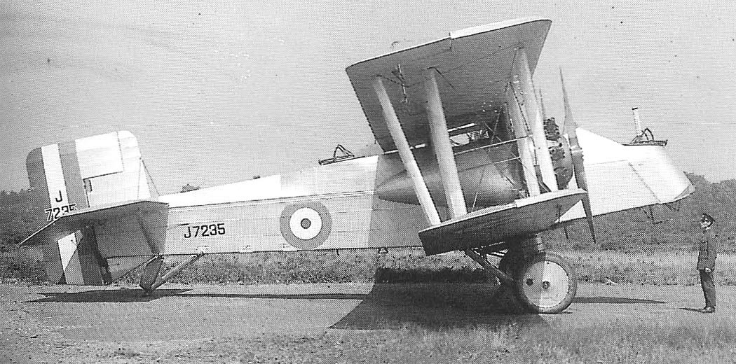
The following year, a modified version appeared – the J7235. The aircraft was completed as a four-seater with 436 hp Jupiter IV engines, replacing the previously installed powerplants. The wingspan was reduced to 62 feet 6 inches (19.05 m), and the fuel capacity was increased.
In 1925, this aircraft was assigned to No. 58 Squadron at Worthy Down for operational trials and comparison with Vickers Virginias, which had been in service since December 1924. Squadron Leader Longton (the CO) arranged to pilot the aircraft at the 1925 Hendon Air Pageant and perform a mock aerial combat with two Gloster Grebe fighters. These were flown by two instructors from CFS – Flight Lieutenant H.A. Hamersley and Flying Officer J. Boothman.
For some time, they practiced displays over Upavon with Longton performing sharp aerobatics in the Bugle bomber. Pilot Officer C. Clarkson flew as an observer on the Bugle and manually worked to maintain pressure in the fuel tanks. The combination of this difficult task and the sharp maneuvers confused him so much that upon landing, he temporarily forgot he wasn’t in a Virginia. He walked straight towards the spinning propeller, was struck by it, luckily flat, and was thrown back. Boothman grabbed him and simply prevented Clarkson from bouncing back under the propeller.
At the Hendon display, Longton showcased astonishing aerobatics in his mock aerial combat with the two Grebes. The aerobatics included Nesterov loops, spins, and even inverted flight. Longton must have relished the maneuverability after flying the stately Virginia bombers.
Besides its excellent maneuverability, the Bugle I also boasted a rather high maximum speed of 120 mph (193 km/h) at sea level and could climb to an altitude of 10,000 feet (3048 m) in 15 minutes 30 seconds. In comparison, the Virginia could only achieve 98.5 mph (158.5 km/h) at sea level.
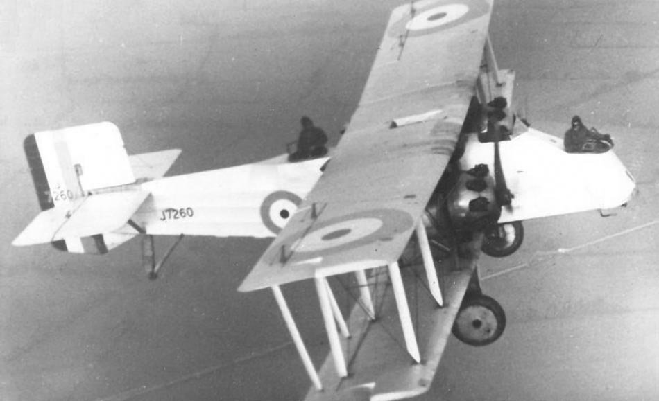
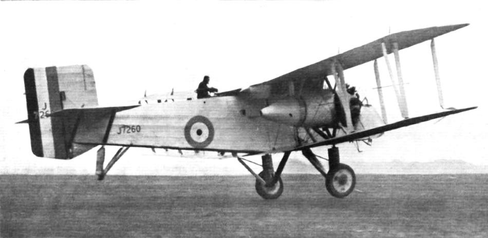
In 1924, two more P.25 Bugle bombers (J7259 and J7260) were built, which were equipped with Jupiter engines and were generally similar to the J7235. One of them, J7260, under the command of Flight Lieutenant W.N. Plenderleith, was demonstrated on February 25, 1917, at Mousehold during an air show dedicated to the formation of the Norwich and Norfolk Flying Club. This allowed the workers to see the results of their labor, although many were deterred from attending due to torrential rain.
Variants and Legacy
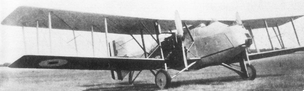
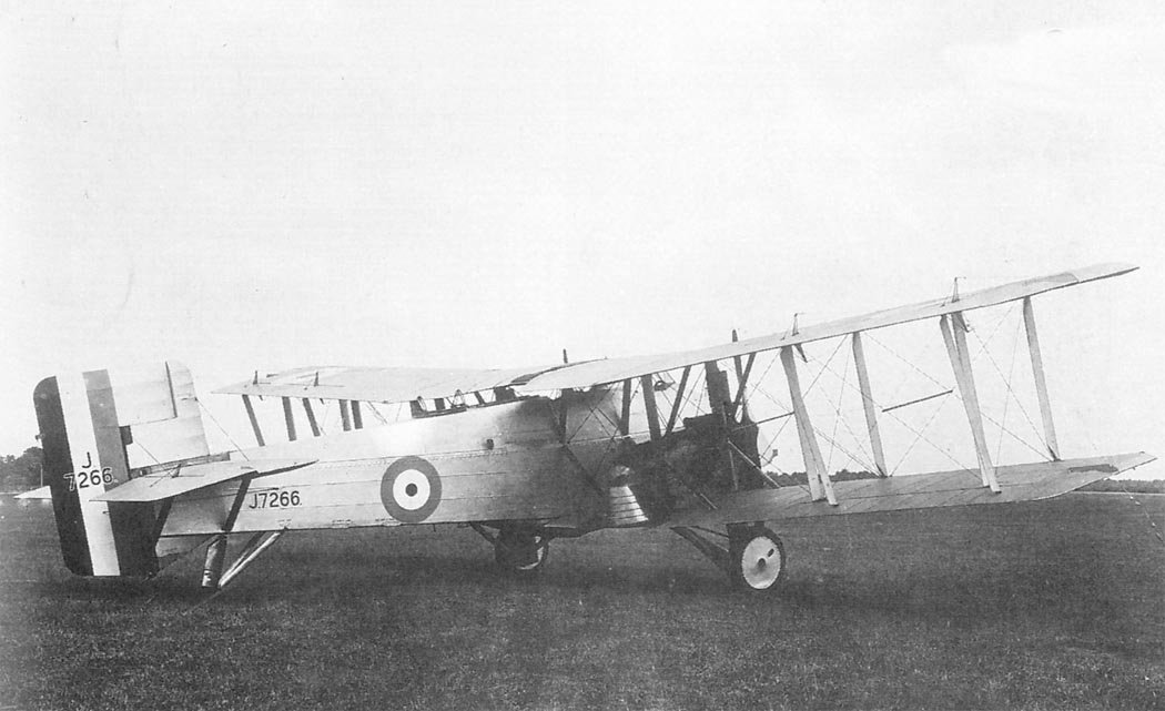
In 1925, another variant of the aircraft was built. The P.25a Bugle II featured 450 hp Napier Lion engines, installed on the lower wing instead of the Jupiters. The fuel tanks of the new variant were relocated from beneath the upper wing to the fuselage.
Subsequently, the machine’s aerodynamics were improved by installing light fairings for the under-fuselage bomb racks. These changes increased the Bugle I’s overall flying weight from 8760 pounds (3974 kg) to 8914 pounds (4044 kg).
Two Bugle Mk IIs, J7266 and J7267, were built, bringing the total number constructed to seven. All Bugle bombers were finished in the standard 1920s aluminum aerolac.
Despite the aircraft’s high performance and exceptional maneuverability, a shortage of funds prevented further construction. However, by continuing its policy of ordering more and more advanced prototypes from Boulton & Paul and other manufacturers, the Air Ministry kept the aviation industry afloat until national security requirements necessitated total production of aircraft.
Technical Specifications
| Modification | Bugle I |
| Wingspan, m | 19.05 |
| Length, m | 12.11 |
| Height, m | 4.77 |
| Wing area, m2 | 85. 94 |
| Normal takeoff weight | 3973 |
| Engine type | 2 Piston engines Bristol Jupiter IV |
| Power, hp | 2 x 425 |
| Maximum speed, km/h | 193 |
| Cruising speed, km/h | 168 |
| Crew, crew members | 4 |
| Armament: | two 7.7-mm Lewis machine guns on Scarff turrets in the nose section and in the rear cockpit. 6×51-kg or 3×10⁴-kg bombs. |
Image and diagram gallery of the Bugle
 Bugle |
 Bugle |
 Bugle |
 Bugle |
 Bugle |
 Bugle |
 Bugle |
 Bugle |
 Bugle |
 Bugle |
 Bugle |
 Bugle |
 Bugle |